How to configure your microscope system for bright, high-contrast fluorescence images
The type and amount of light hitting the sample plane will make or break a fluorescence microscopy experiment. It is undoubtedly an important property of the microscope set up to be optimised, but some aspects can be overlooked, leading to reduced image quality. Where our previous white paper guided microscopists on how to measure irradiance at the sample plane, we now set out to advise how it can be improved to deliver quality images and insightful data.
Find out:
• How to increase irradiance
• Which type of illumination system delivers highest irradiance
• Which microscope components should also be considered
• Why stronger irradiance is not always optimum

Introduction
Many factors affect image quality, and in fluorescence microscopy the light hitting the sample plane can make all the difference between an experimental breakthrough and inconclusive results.
In our previous white paper, we discussed how to measure the amount of light at the sample plane – known as irradiance.1 By offering a standardised method, this enables microscopists to quantify and compare the amount of light at the sample plane and therefore directly compare systems to find their ideal solution.
Now we have clarity on what we are measuring and how, let us return to one of the key topics in fluorescence microscopy illumination: how to boost illumination of useful light to the optimum levels required for the experimental set up. When we speak of ‘useful light’, we do not only mean the amount of light, but also the wavelength and exposure duration. By ensuring these properties are optimal, it is possible to significantly improve experimental success.
Choosing the right illumination system
When looking to improve sample illumination, the first part of the microscope to address is of course the illumination system, and the industry is currently experiencing a transition towards newer technology.
Since the first LED illumination system for fluorescence microscopy appeared on the market in 2006, laboratories are increasingly moving towards this modern light source due to their many benefits. But how does the irradiance of modern LED illumination systems currently compare to conventional mercury and metal halide lamps? Historically, the irradiance of LEDs was considered low, and although this can still haunt its reputation, the technology has now matured and LEDs are equivalent or brighter in many areas of the spectrum. At the lower end of the spectrum, LED irradiance has surpassed that of the metal halide, however in the green region, LED irradiance is still improving. This ‘Green Gap’ is well known in the LED technology industry and results from a lack of suitable semiconductor materials. The good news is that LED efficiency is improving in line with Haitz’s law, which states that the irradiance of light generated by an LED increases by a factor of 20 each decade.2 Moreover, as we will go on to explain, this is not the limitation it might at first seem, and in the case of live cell imaging it is even an advantage.
LED technology and the drive for increased irradiance
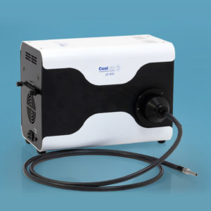
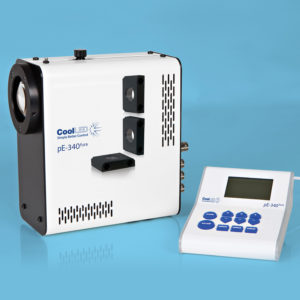
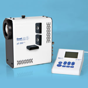
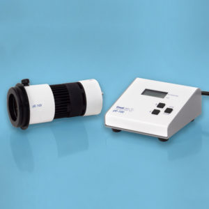
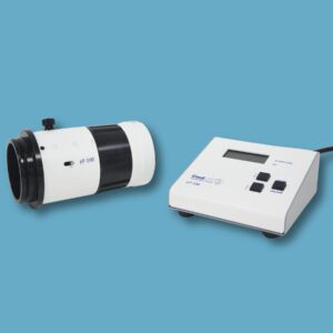
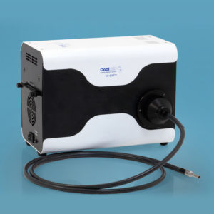
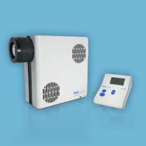
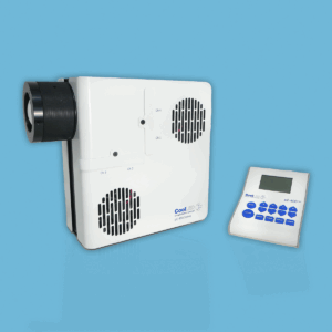
Today’s LED illumination systems for life sciences are ideal for the vast majority of widefield fluorescence microscopy applications. When choosing an illumination system for applications demanding higher irradiance, direct fit options are available which fit directly to the back of the microscope instead of using a liquid light guide, thereby reducing the losses incurred (Figure 1). Not only do these avoid the loss of irradiance as the liquid light guide degrades over time, but they are also more cost-effective. This is because they avoid the need to replace the liquid light guide when it comes to the end of its life and the associated concern of when that might be. If a liquid light guide must be used, irradiance can be increased by switching to a 1.5 m instead of a 3 m version and optimising the collimator settings for Köhler illumination.
As the growing efficiency of LEDs leads to irradiance gains, LEDs now typically exhibit above 30% efficiency, whereas traditional lamps are mostly below 10%. As efficiency increases this also reduces heat output, which has an added benefit, since reducing operating temperature is known to increase LED lifetime. Boosting irradiance and extending the lifetime through thermal management is such a significant factor when designing LED Illumination Systems, CoolLED’s work focuses on a range of innovations in this area – for example, reducing LED temperatures through unique heatsink designs which conduct heat away from the LED much more efficiently.

Choosing the best filters for your application
Alongside selecting a modern illumination system and switching to direct fit models, irradiance can be increased through optimising other aspects of microscope configuration such as optical filters.
Selecting the best optical filters increases irradiance of useful light. The function of optical filters is to block unwanted light whilst allowing light at favourable wavelengths to pass (i.e. the optimum wavelengths for exciting the selected fluorophore). Filters optimised for a defined set of fluorophores will expose the sample only to the most suitable wavelengths, blocking background noise and leading to brighter and high-contrast images. Historically, filters have been designed for mercury and metal halide lamps and we often come across these being used with new LED illumination systems, which can compromise image quality, with knock-on effects for data interpretation. Single-band filters are now available that are matched to the spectra of LEDs and popular fluorophores. When used with LED illumination systems, these increase the signal to noise ratio for single-colour imaging and minimise bleed-through to enhance multi-colour imaging. An example of this can be seen in Figure 2.
Once a benchmark is created by following the protocol previously outlined1 and quantifying the total unfiltered power, it is then possible to calculate and compare irradiance at the sample plane with different filters in place, to determine how these affect irradiance for the individual set up.


Figure 2: Selecting the correct optical filters enhances image brightness and contrast.
Making better use of light
In addition to the illumination system and optical filters, other microscope components also have the means to impact the brightness of images. For example, higher quality objectives permit more light to pass to and from the sample (Figure 3) while a more sensitive camera will generate brighter images from samples emitting lower levels of signal. Making better use of light in this way and lowering the excitation irradiance reduces photobleaching and phototoxicity and is ideal for live cell imaging.

Less is more in live cell imaging
Although we have discussed how several avenues can be explored in order to maximise irradiance, it is important to consider whether a higher irradiance is in fact necessary.
Whilst the industry strives for higher irradiance, in some cases lower irradiance may be vital. For example, certain fluorophores and experimental conditions can lead to photobleaching, destroying the fluorescence signal. Fluorescence microscopy involves exposing live cells to light levels many times higher than experienced in nature, and reduced irradiance will avoid artefacts and data inaccuracies resulting from phototoxicity. To combat these issues, LED illumination systems are recommended since they can be more wavelength specific. This allows the excitation wavelength to be matched to the filter set and fluorophore, thereby reducing sample exposure to unwanted light. The LED power can also be finely tuned between 0-100% in 1% increments and can therefore be modulated to suit exact requirements. Furthermore, with TTL triggering, the light source is triggered only for the period required for camera exposure and not a microsecond longer, which is particularly beneficial in time lapse experiments. The topic of optimising illumination irradiance has really come to the fore as a challenge for live cell imaging, and we highly recommend further reading.3,4 We also have a white paper available on this topic, which explores in more detail how LED illumination reduces photodamage (read the white paper here).
Summary
We are often asked about power and irradiance of LED illumination systems, and while the technology is indeed continuing to improve, the answer is not so simple and it is important to understand the bigger picture. Firstly, if an improvement is necessary in image brightness and contrast, several microscope components should be taken into consideration in addition to the illumination system. In particular, optical filters dictate how much useful light excites the fluorophores in use. Secondly, live cell imaging in fact benefits from improved control in irradiance rather than an overall irradiance increase, and in these cases modern LED illumination systems can enhance image quality by other means. Interestingly, the level of irradiance is also tied to the homogeneity of illumination across the field of view and we will explain this in future.
In summary, each application has unique requirements, so for brighter images with better contrast we would recommend discussing this topic in more detail with our technical support or your local microscope supplier.
For more information on irradiance or filters optimised for LED illumination systems; or if you would like a demonstration, please contact info@cooled.com
References
1 – CoolLED. (2019). Measuring illumination intensity with accuracy and precision.
2 – “Haitz’s law”. Nature Photonics. 1: 23. 2007. DOI:10.1038/nphoton.2006.78.
3 – Icha, J. et al. (2017). Methods, Models & Techniques. DOI 10.1002/bies.201700003
4 – Laissue, P. et al. (2017). Nature methods. DOI: 10.1038/nmeth.4344